The following physical quantities are measured in
an electrical circuit;
Current,:
Denoted by I measured in Amperes (A).
Resistance
,:
Denoted by R measured in Ohms ( W
) .
Electrical
Potential Difference ,: Denoted by V
measured
in volts. (v)
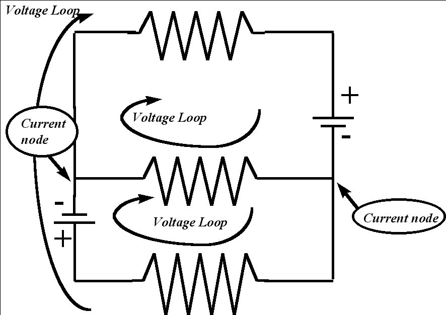
Three basic laws govern the flow of current in an electrical circuit :
1. Ohm's Law
2. Kirchhoff's Voltage Law Conservation of Energy.
3. Kirchhoff's
Current Law Conservation of Charge .
Simple circuits are categorized in two type :
For circuits with series and parallel sections, break the
circuit
up into portions of series and
parallel, then calculate values for these portions, and use these
values to calculate the resistance of the entire circuit. That is,
first, for each individual series path, calculate the total
resistance
for that path.
Second, using these values, by assuming that each path as a single
resistor, calculate the total resistance of
the circuit.
We can apply the methods for solving linear systems to
solve
problems involving electrical circuits. In a given circuit
if enough values of currents, resistance, and potential
difference
is known, we should be able to find the other unknown values of these
quantities.
We mainly use the Ohm's Law , Kirchhoff's
Voltage
Law and Kirchhoff's current Law.
Example: Find the currents in the circuit for the following network.
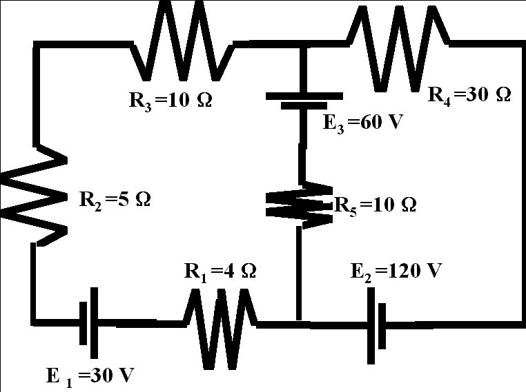
Solution :
Lets
assign currents to each part of the circuit between the node
points.
We have two node points Which will give us three different
currents.
Lets assume that the currents are in clockwise direction.
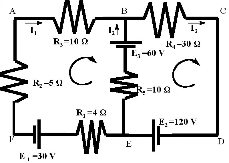
So the current on the segment EFAB is I1, on the segment BCDE is I3 and on the segment EB is I2
Using the Kirchhoff's current Law for the node B yields the equation
For the node E we will get the same equation.Then we use Kirchhoff's voltage law
-4 I1+ (-30) -5 I1 - 10I1 -60 +10I2 =0
When through the battery from (-)
to (+), on the segment EF, potential difference
is -30, and on segment FA moving through the resistor
of
5W
will result in the potential difference
of -5 I1 and in a similar way we can find the
potential
differences on the other segment of the loop EFAB.
In the loop BCDE, Kirchhoff's voltage law will yield the following equation:
-30 I3+ 120-10I2+60 =0
Now we have three equations with three unknowns:
I1
+ I2
-
I3 =0
-19 I1 +10 I2
=
90
-10
I2 -30 I3
= -180
This linear system can be solved by methods of linear Algebra. Linear Algebra is more useful when the network is very complicated and the number of the unknowns is large.
The system above has the following solution: