The following physical quantities are measuered in
an electrical circuit;
Current,: Denoted
by I measured in Amperes (A).
Resistance ,:
Denoted by R measured in Ohmes ( W
) .
Electrical Potential Difference ,:
Denoted by V measured in voltes.(v)
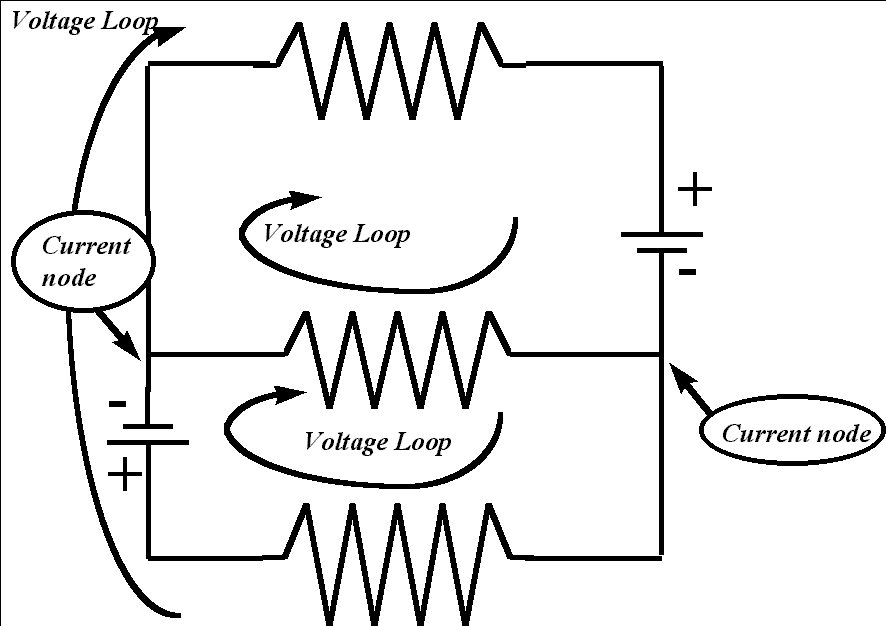
The flow of current in an electrical circute is goverened by three basic laws:
1. Ohm's Law
2. Kirchoff's Voltage Law Conservation of Energy.
3. Kirchoff's
Current Law Conservation of Charge .
one volte = ( one ampere ) X one (ohm)
Electric current is a measure of the amount of charge which pass through
a point in any given instance of time. Or how
much electricity is going through the wires. Current is measured in
Amperes (amps).
One amp is technically defined as one coulomb of charge passing a point
in one second.
I = q/t
I = current (A or Cs-1)
q = change in charge (C)
t = change in time (s)
Georg Simon Ohm devised a formula that relates the voltage,
current, and resistance of a circuit.
V = I x R
V = Voltage (V)
I = Current (A)
R = Resistance (ohms)
Resistance is a measure of the opposing force which is
applied to electricity in a circuit. The resistance of the wires in
the circuit can be ignored, because
it is very low. Motors, lightbulbs, and heating coils are all examples
of resistors.
How to calculate the total resistance in a series circuits ?
A series circuit is a circuit that has only one pathway.
There are no branches in the circuit, and hence the electricity can
only travel in one route.
The total resistance in
a series circuits is the sum of all the values for each
individual resistor.
$ R_{total } = R_1 + R_2 + R_3 + \cdots + R_n $
How to calculate the total resistance in
a parallel circuits?
Parallel circuits are circuits which have more than one branch, or
pathway which electricity can travel through.
The total resistance is the reciprocal of the sum of the
reciprocals of each resistor.
$ \displaystyle \frac { 1 } { R_{total } } = \frac
{ 1 } { R_1 } + \frac { 1 } { R_2 } + \frac { 1 } { R_3 } + \cdots +\frac
{ 1 } { R_n } $
For circuits with series and parallel sections:
First, For each individual series path, calculate the total
resistance for that path.
Second, using these values, by assuming that each path as a single resiator,
calculate the total resistance of
the circuit.
Break the circuit up into portions of series and
parallel, then calculate values for these portions, and use these
values to calculate the resistance of the entire circuit.
=====================
1. The current does not vary as it passes through each individual resistor.
2. In a series circuit the current is the same at any particular point on the circuit.
3. The voltage in a series circuit, however, does not remain constant.
4. The voltage drops across each resistor.
5. The total voltage drop across all resistors will add up to the voltage
off the power source, eg. a battery etc.
6. In parallel circuits current is spread along the various branches.
The current in one
branch will not be the same as in other branches
(unless of course all the resistances are
the same).
7. The sum of the current in each individual branch will add up to give
the total
current of the circuit.
8. The voltage in parallel circuits is actually the same for each branch,
and equal to the
voltage of the power source.
In series circuits, current is constant, but the
voltage is different, and adds to the total voltage.
In parallel circuits, the voltage is constant, but
the current varies, and adds up to the total current in the circuit.